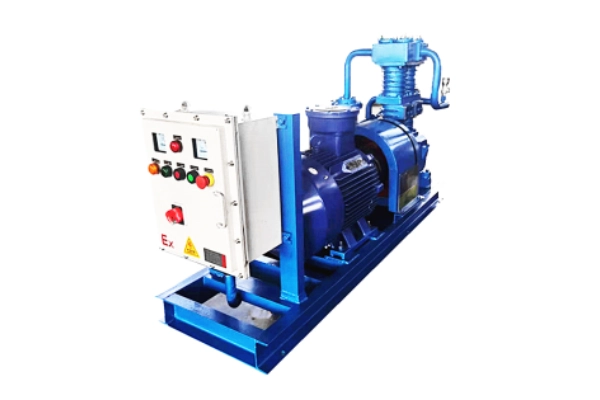
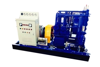
This gas unloading compressor is specifically designed for gas loading and unloading operations involving tank trucks and gas cylinder groups. It employs a highly efficient and reliable structure, enabling rapid gas pressurization, unloading, and residual liquid recovery.
The equipment operates stably and is easy to use, featuring comprehensive safety protection and sealing performance, and is suitable for various industrial gas conditions.
It is widely used in chemical, energy, and gas filling stations to improve unloading efficiency and ensure safe and reliable operations.
It is widely used in chemical, energy, and gas filling stations to improve unloading efficiency and ensure safe and reliable operations.
Main Technical Parameters of Liquid Ammonia Loading and Unloading Compressors
No.
Model
Motor Power(KW)
Overall Dimensions(L×W×H)mm
Loading /unloading capacity(t/h)
1
ZW-0.6/16-24
15
~1100×700×900
~17.5
2
ZW-0.8/16-24
18.5
~1100×700×900
~23
3
ZW-1.0/16-24
22
~1100x700x900
~29
4
ZW-1.5/16-24
30
~1400x900x1180
~43
5
ZW-2.0/16-24
37
~1400×900×1180
~58
6
ZW-2.5/16-24
45
~1400x900x1180
~73
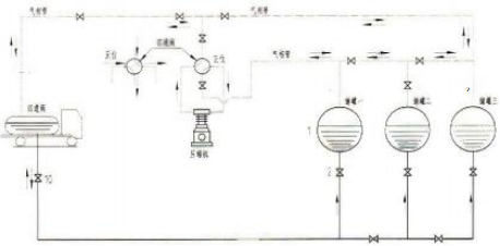
Unloading process flow diagram
Liquid transport
Initially, the liquid phase pipe between the tank truck and the storage tank is opened. If the liquid level in the tank truck is higher than that in the storage tank, it will automatically flow into the storage tank and stop flowing when equilibrium is reached. If the liquid level in the tank truck is lower than that in the storage tank, the compressor is started directly, with the four-way valve in the positive position. Gas is drawn from the storage tank, pressurized, and then discharged into the tank truck through the compressor. At this time, the pressure in the tank truck increases, and the pressure in the storage tank decreases, causing the liquid in the tank truck to flow into the storage tank under the action of the pressure difference. (See diagram below)
Waste gas recovery
After unloading, some residual gas and saturated gas remain at the bottom of the tanker. When the user needs to recover this portion of the medium, the four-way valve is reversed and the liquid phase pipeline is closed. At this time, the remaining saturated gas in the tanker is drawn in by the compressor, pressurized, and discharged into the storage tank. The pressure in the storage tank rises, exceeding the gas phase saturation pressure, causing the gas to liquefy, achieving the recovery purpose. Meanwhile, the pressure inside the tanker drops, and the liquid phase continues to vaporize until all liquid has vaporized and the gas phase pressure drops to the compressor’s maximum allowable operating value, at which point recovery stops. (Note: A cooler can be added to the exhaust end to facilitate residual gas recovery.)
Working principle of four-way valve
When the four-way valve is in the position shown in Figure a, end A is the intake, and gas flows from A to B, through the connecting pipe, intake filter assembly, compressor intake pipe, compressor, compressor exhaust pipe, and end D to end C, which is the exhaust end.
When the four-way valve is in the position shown in Figure b, end C is the intake, and gas flows from C to B, through the connecting pipe, intake filter assembly, compressor intake pipe, compressor, compressor exhaust pipe, and end D to end A, which is the exhaust end.
Compressor inlet and outlet pressure selection
Temperature(℃)
Atm(kg/cm²)
Temperature(℃)
Atm(kg/cm²)
20
8.4585
30
11.512
22
9.0125
32
12.212
24
9.594
34
12.943
26
10.204
36
13.708
28
10.843
The saturated vapor pressure of liquid nitrogen at 20-36℃
At higher temperatures, the saturated vapor pressure of liquid ammonia is higher, so a model with an inlet pressure of 16-24 (exhaust pressure) is selected to meet the requirements of the high-temperature operating environment.
Compressor displacement calculation
The specific flow rate calculation is quite complex and needs to be determined based on calculation formulas and experience. This section only introduces a simple calculation method: taking the unloading of a 15-ton tanker truck in one hour as an example.
Calculate tank truck volume
Based on the provided operating conditions, first determine the total volumetric flow rate required to unload 15 tons of liquid ammonia from the tanker truck in one hour.
The specific gravity of liquid ammonia is 0.618, therefore the volume of 15 tons of liquid ammonia is: 15 ÷ 0.618 = 24.272 m³. Since the tanker truck cannot be filled completely, it is generally filled to about 80% of its capacity. Therefore, the tanker truck volume is 24.272 ÷ 0.8 = 30.34 m³. Thus, the total volume of the tanker truck is 30 m³.
Calculate exhaust volume
Because the compressor must first establish a pressure differential before unloading liquid ammonia from the tanker truck to the storage tank, and this typically takes 15 minutes, the actual unloading time is only 45 minutes. Therefore, the required discharge volume is 30 ÷ 45 = 0.66667 m³/min. After the gas is pressurized from 1.6 MPa to 2.4 MPa by the compressor, its volume will decrease to approximately 0.66667% of its original volume (16 ÷ 24). Therefore, the compressor discharge volume is 0.66667 ÷ 0.66667 = 1 m³/min.Based on the above calculations, the recommended compressor model is ZW-1.1/16-24